However, this method unavoidably subjects the girth welded seamless pipe joints to plastic strain cycles during the installation process. As a consequence, the structural integrity of the pipeline during and after installation is a cause of concern.
Additionally, because the welding process inevitably produces intrinsic and/or occasional defects, the defect tolerability of the seamless pipeline girth joints has become the key issue in applying the reel-laying technique. Thus, a need has arisen to ensure that unsafe defect sizes are within the detection limits of modern non-destructive testing in order to assure adequate confidence in their sizing and positioning.
In recent decades, the need to quantify the safety of defective welded structures for their intended service conditions has become part of the development of Engineering Critical Assessment (ECA) methods. These methods seek to produce reliable and widely accepted procedures for assessing defective structures. Such procedures are dedicated to stress-based conditions and, if applied directly to a displacement controlled situation involving large strains, such as pipeline reel-laying methods, would produce overly conservative predictions.
On the other hand, experimental evidence often reveals that defect tolerability exists in instances involving the offshore installation of pipelines subjected to large cyclic plastic strains. To overcome such discrepancies and to provide useful tools for evaluating the effective defect tolerability of girth joints that will be subjected to the reel-laying technique, various studies have been initiated to develop a strain-based ECA. A first proposal of procedure has resulted and been included in DNV OS F101 in the form of corrections to the calculation route of BS 7910 Level 3.
Also, alternative solutions to standard toughness methods testing solutions have been proposed. In particular, short notch SENB specimen and Single Edge Notch Tensile (SENT) specimen are possible testing solutions for reducing conservatism, but are not included in standards for material testing. It is worth mentioning that the effect of various cycles of pipeline strain is taken into account in a rough manner only.
Currently, few data are available regarding the actual reliability of such calculation routes. Further development of strainbased ECAs have been subsequently promoted and such assessment methods are beginning to be accepted by companies involved with offshore installation techniques that imply large deformations.
In recent years, Tenaris installed facilities at its Tamsa mill for the production of double-joint pipe strings to enable the delivery of pipes with a total length exceeding twenty meters obtained through in-shop girth welding of two seamless pipes. The production facility includes a dedicated laboratory for double-joint product development and for establishing proper welding procedure specifications that respond to the most severe requirements and the most challenging applications.
In order to investigate the defect tolerability of Tenaris double-joint pipes destined for installation using reel-laying, a dedicated mechanical characterization was performed that focused on tensile and toughness properties. Tensile testing of the base material showed a discontinuous stress/strain curve with a yield strength of 466MPa, tensile strength of 554 MPa and a satisfactory level of Y/T ratio (Y/T = 0.84).
Weld metal proved to guarantee a satisfactory overmatching level with respect to the base material as demonstrated by both hardness and tensile tests results. In particular, cross weld strip specimens with, and without weld reinforcement were used and both exhibited necking and rupture in base material, far from the welded joint.
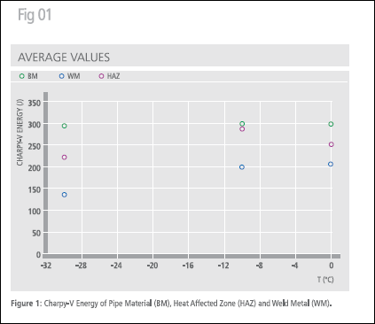
With regard to the toughness testing results of impact CharpyV tests performed using through-thickness notched specimens with notch-in-base material (BM), weld metal (WM) and in heat-affected zone (HAZ) crossing fusion line, good behaviour of the double joint was demonstrated not only at the assumed operational temperature of -10C, but at even lower temperatures (Figure 1).
CTOD tests carried out at -10C demonstrated a satisfactory level of toughness; in particular using through thickness notched specimens according to BS 7448 part II minimum CTOD values of 1.34 mm, 0.56 mm and 0.80 mm were achieved in BM, WM and HAZ respectively.
Toughness characterization has been completed with the determination of the J resistance curve by means of Single Edge Notch Test (SENT). Also in the worse condition, deep notch in weld metal, very satisfactory values of J-resistance are encountered with, for instance, Jresistance values higher than 600 MPa mm in correspondence of ductile tearing extent ?a 0.6 mm.
ECA Approach
The adopted ECA approach originated from the BS 7910 procedure which implements the Failure Assessment Diagram (FAD) method. The reel-laying method is predominately characterized by displacement-controlled situations. Since FAD-based assessment of BS 7910 is formulated for load control situations, the direct application of the procedure to a reeled girth joint would produce overly conservative assessments with no practical usefulness of the results. To overcome this problem, numerous research efforts were employed to elaborate corrections to the assessment procedure to convert it into a strain-based assessment.
The main solutions adopted for the assessment are:
Ductile tearing assessment. The material is expected to have ductile behaviour in presence of defects. The assessment is required to consider the amount of possible ductile tearing that defects may experience during installation
Material specific FAD required. The close relation between the Jresistance curve and material stress strain curve of sub-level B of BS 7910 is regarded to be qualitatively correct.
Low constraint toughness test. Material toughness, J-resistance curve, is determined by means of a Single Edge Notch Tensile (SENT) specimen, since the level of crack tip constraint in such a test is considered to be representative of the constraint conditions of a defected girth joint subjected to reeling.
Plastic collapse cut-off corresponding to ultimate strength. Plastic Collapse is predicted to occur when applied stress at net section reaches material ultimate strength instead of flow stress as stated in BS 7910.
Strain Concentration Factors (SNCFs). All the relevant strain concentration phenomena have to be considered to magnify the applied strains. In calculating the SNCFs from elastic SCF expression, the Neuber hypothesis can be assumed as valid.
Material toughness of multi-plastic strain cycles. Materials, after suffering plastic deformation cycles ended by a compressive load, are considered to have the same toughness resistance of the virgin materials.
Crack-driving force of multi-plastic strain cycles. After a compressive deformation, the whole positive strain increment has to be considered active in terms of crack-driving force. No residual crack-driving force is considered to act on the defected zone in consequence of the previous strain cycles.
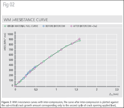
A lack of knowledge is observed in robust methods dealing with material toughness when the defective component is subjected to cyclic plastic deformations. Small-scale special tests have been performed to offer a first rough experimental support to the hypothesis about material toughness of multi-plastic strain cycles. Traditional Compact Tensile (CT) specimens have been adopted to determine the J-resistance curve of both weld metal and heat affected zone.
Determination of the whole J-resistance curve is accompanied by the determination of the same curve on samples where the application of increasing loads is interrupted interposing a compressive load, approximately corresponding to a 2% strain in the base material, as typical for the application considered (that is reel-laying technique). Main result was that the material under investigation, both in weld metal and in heat affected zone, after inter-compression follows substantially the same Jresistance curve corresponding to the same material before inter-compression, as shown in Figure 2.
Loading Conditions Analysis
To perform the ECA, the first step consists of defining the strain cycle applied to the girth joint during reeling installation. As a common practice, it is often required that the pipeline successfully passes a Simulated Spooling and Straightening Test" where the strain history is conservatively enlarged and the larger deformation cycle is repeated twice. In agreement with the guidelines from TWI, DNV and SINTEF, all the positive strain increments are considered as active in terms of crack driving force, and then are taken into account to evaluate the load acting on the flaw.
The following dimensions have been considered for the reeling simulator formers: spooling former radius (= hub radius) = 8.23 m; Straightening former = 55.84 m. As a consequence, the following total amount of positive strain increments will interest the most strained position of the pipeline: Simulated Spooling Positive Strain Increment = 1.66%; Simulated passage on the aligner Positive Strain Increment = 1.90%.
Tolerable Defect Size Determination
A defective double joint subjected to a reel-laying installation is considered to have "failed" if an unstable fracture or a plastic collapse occurs or if total amount of subcritical crack growth exceeds 2.0mm.
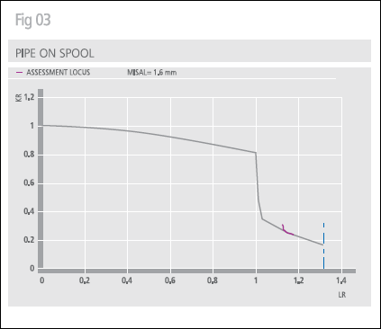
First of all, the maximum tolerable defect size for a reel-laying installation has been calculated assuming a maximum misalignment of 1.6 mm. This value is expected to exceed the maximum value fixed as allowable by the internal good workmanship criteria of Tenaris for the production of double joints. In Figure 3, an example of defect assessment is shown. A defect of initial dimensions a0 = 6.0 mm, 2c0 = 25.0 mm, when reeled on the hub (Figure 3, top) is predicted to suffer an initial sub-critical tearing (?a1 = 0.54 mm) with consequent stabilization (assessment locus crossing safe area borderline). Also in correspondence of the passage on the aligner a certain ductile tearing (?a2 = 0.54 mm) is predicted to occur with final stabilization of the defect (Figure 3, bottom). Finally the analyzed defect is predicted to suffer a total sub-critical ductile tearing of ?atot = 1.08 mm, during installation operations.
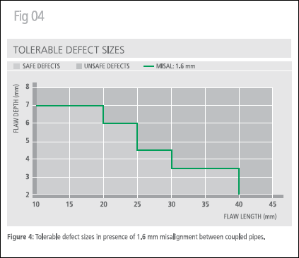
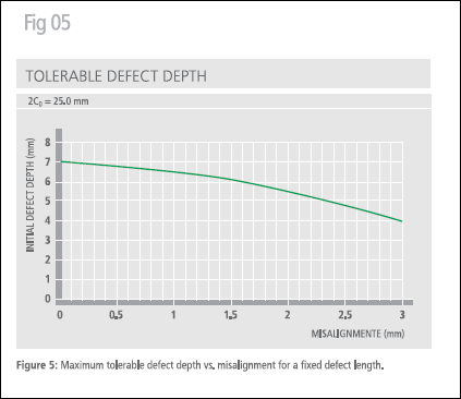
In Figure 4, the obtained set of maximum allowable defect dimensions has been plotted. Analogous calculations have been performed for other values of maximum misalignment. In order to highlight the effect of misalignment as cause of strain concentration which reduces the maximum tolerable defect, the maximum tolerable defect depth has been plotted in Figure 5 against the misalignment.
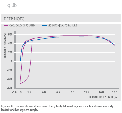
To have the adequate certainty of the conservativeness of the assessment procedure it is recommended it be validated by means of large scale tests. Six segment tests were performed with the two-fold aim of verifying the predictions obtained with the established ECA procedure and the actual load capability of the tested girth joint after the application of multiple plastic strain cycles. Test results demonstrated that the set up ECA procedure produces reliable and conservative predictions, with actual ductile tearing extents lower than the predicted ones.
Figure 6 also evidences that the straining cycles did not damage the straining and load capability of the segments of Tenaris double joint.
Conclusion
An Engineering Critical Assessment of seamless double-joint pipes for deepwater applications that use girth welded joints and are subjected to large cyclic plastic strains when installed using the reel-laying method demonstrates that the double joints exhibit good behaviour and do not suffer any special, or unexpected damages as a consequence of being subjected to multiple plastic straining cycles.
*This article was written by L.F. Di Vito, G. Mannucci, G. Demofonti, Centro Sviluppo Materiali S.p.A. and G. Cumino, A. Izquierdo, F. Dagurre, H. Quintanilla and M. Tivelli of Tenaris.
Oil Review Middle East 2005